
Electrochemistry and Corrosion
Master the principles of electrochemistry, galvanic and electrolytic cells, reference electrodes, conductometry, advanced batteries and fuel cells, and the mechanisms and control of corrosion.
Before you start: Basic chemistry concepts including oxidation and reduction states; Fundamental knowledge of solutions, concentrations, and stoichiometry; Basic physics concepts of electrical current, voltage, and resistance.
Your path through this module
- Fundamentals of Electrochemical Cells: Separating oxidation and half-cell reactions to generate electrical energy via a spontaneous redox process.
- Reference Electrodes and Electrode Systems: Using secondary reference electrodes like the Calomel electrode for convenient potential measurements.
- Electrochemical Series and Its Applications: Arranging electrodes in order of reduction potential to quantitatively predict chemical reactivity and cell spontaneity.
- Conductivity and Conductometric Measurements: Relating cell geometry and ion mobility to bulk solution conductivity via the cell constant.
- Advanced Batteries and Fuel Cells: Intercalation-based energy storage in lithium batteries and continuous reactant feed in fuel cells.
- Corrosion Mechanisms and Theories: Treating environmental degradation of metals as localized short-circuited electrochemical corrosion cells.
- Corrosion Control and Metal Finishing: Forcing a corroding metal to act as a cathode or depositing protective metallic coatings via electrolytic and autocatalytic routes.
Fundamentals of Electrochemical Cells
Electrochemistry is the branch of chemistry that deals with the interconversion of electrical energy and chemical energy. Depending on the direction of energy conversion, electrochemical systems are classified into two primary categories: electrolytic cells and galvanic cells.
Electrolytic vs. Galvanic Cells
The fundamental differences between an electrolytic cell and a galvanic cell are summarized in the table below:
| Electrolytic Cell | Galvanic Cell |
|---|---|
| Converts electrical energy to chemical energy. | Converts chemical energy to electrical energy. |
| Requires an external electromotive force (EMF). | Produces its own EMF. |
| Anode is positive (), cathode is negative (). | Anode is negative (), cathode is positive (). |
| Discharge of ions occurs at both electrodes. | Discharge of ions occurs only at the cathode. |
| Involves a non-spontaneous redox reaction. | Involves a spontaneous redox reaction. |
| Generally irreversible. | May be reversible. |
The Daniell Cell
The Daniell cell is a classic example of a galvanic cell that harnesses a spontaneous redox reaction to generate electrical energy. It consists of two half-cells: a zinc rod immersed in a zinc sulfate () solution acting as the anode, and a copper rod immersed in a copper sulfate () solution acting as the cathode.
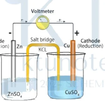
Figure: Galvanic cell diagram with salt bridge
Galvanic cell diagram showing an anode half-cell on the left with a Zn rod immersed in ZnSO4 solution, labelled Anode (Oxidation) and Zn. A cathode half-cell on the right with a Cu rod immersed in CuSO4 solution, labelled Cathode (Reduction) and Cu with a plus sign. An inverted U-shaped salt bridge containing KCL connects the two beakers. A voltmeter is connected at the top with arrows indicating electron flow from Zn to Cu.
-
Anode Reaction (Oxidation): Zinc has a greater tendency to undergo oxidation than copper. Zinc atoms lose electrons and enter the solution as ions, leaving the electrode negatively charged.
-
Cathode Reaction (Reduction): Copper ions in the cathodic compartment accept electrons and are deposited as copper metal at the positive electrode.
-
Overall Cell Reaction: Combining the two half-reactions yields the spontaneous cell reaction:
In the external circuit, electrons flow from the zinc electrode (anode) to the copper electrode (cathode). Consequently, conventional electrical current flows from the copper electrode to the zinc electrode.
Cell Representation
A galvanic cell is conventionally represented using IUPAC notation, where the anode is written on the left and the cathode on the right. A single vertical line () denotes a phase boundary, and a double vertical line () represents the salt bridge:
Function of the Salt Bridge
A salt bridge is an inverted U-tube filled with an electrolyte (such as or ) in an agar-agar gel that connects the two half-cell compartments. Its key functions include:
- Electrical Contact: It completes the electrical circuit by allowing ionic conduction between the two half-cells without mixing the bulk solutions.
- Charge Balance: As oxidation proceeds at the anode, excess ions accumulate, while reduction at the cathode depletes ions and leaves behind excess sulfate () anions. The salt bridge prevents charge accumulation by allowing anions (e.g., ) to migrate into the anodic compartment and cations to migrate into the cathodic compartment.
- Elimination of Junction Potential: It minimizes or completely eliminates the liquid junction potential that arises at the contact boundary of two dissimilar electrolyte solutions.
Types of Electrodes
Electrode systems are categorized based on their physical nature and mechanism of potential generation:
- Metal-Metal Ion Electrode (e.g., or )
- Gas Electrode (e.g., Standard Hydrogen Electrode)
- Metal-Metal Insoluble Salt Electrode (e.g., Calomel electrode)
- Redox Electrode (e.g., Platinum electrode in solution)
- Ion-Selective Electrode (e.g., Glass electrode for measurement)
Reference Electrodes and Electrode Systems
Bridge: Building on single half-cell potentials, this topic introduces reference electrodes to measure unknown single electrode potentials and pH. The new idea: Using secondary reference electrodes like the Calomel electrode for convenient potential measurements. Objectives: Classify types of electrodes; Describe the construction, working, and limitations of a Standard Hydrogen Electrode (SHE); Explain the Saturated Calomel Electrode (SCE) and its application in potential measurements; Detail the glass electrode mechanism and its use in pH determination
Classification of Electrodes
1. Metal-Metal Ion Electrode
A metal is immersed in its own ionic solution, resultant electrode is called metal-metal ion electrode. Such as Zinc in Zinc sulphate, copper in copper sulphate , .
2. Gas Electrode
In gas electrode, gas is passed through an inert electrode like platinum which is immersed in a solution containing its own ion. Eg. Hydrogen electrode .
3. Metal-Metal Insoluble Salt Common Ion Electrode
In metal-metal insoluble salt electrode, metal is covered with a paste of its insoluble metal salt which is in contact with a solution containing a common ion with the insoluble salt. Eg. Calomel electrode, Mercury in contact with an insoluble precipitate of which is in contact with solution, .
4. Redox Electrode
An electrode in contact with a redox system is called redox electrode. Eg: Platinum electrode immersed in the mixture of Ferric chloride and Ferrous Chloride Solution .
5. Ion Selective Electrode
In this electrode, the sensing part of the electrode is made up of an ion selective membrane. Eg. Glass electrode consists of an ion selective membrane sensitive to ions.
Standard Hydrogen Electrode (SHE)
It consists of inert platinum electrode dipped in . Which is in contact with gas at pressure at .
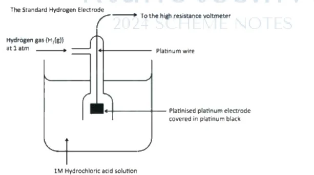
Figure: Diagram of The Standard Hydrogen Electrode (SHE)
Diagram of The Standard Hydrogen Electrode (SHE). It shows a beaker containing 1M Hydrochloric acid solution, an outer glass jacket surrounding an inner tube through which hydrogen gas (H2(g)) at 1 atm enters, a platinum wire extending from the top and connected to the high resistance voltmeter, and a platinised platinum electrode covered in platinum black at the bottom inside the jacket.
Characteristics of SHE
- Its potential is arbitrarily fixed as zero.
- It is a reversible electrode, i.e. it can function as an anode or cathode depending on the nature of the other electrode to which it is connected.
If the potential of the coupled electrode is more than zero, oxidation takes place at SHE and it functions as an anode, it can be represented as:
Cell reaction:
If the potential of the coupled electrode is less than zero, reduction takes place at SHE and it functions as a cathode, it can be represented as:
Cell reaction:
Drawbacks of SHE
- It is very difficult to set up.
- It cannot be used as a reference electrode if the solution contains reducible substances such as copper, silver etc.
- It causes poisoning of the Pt foil.
- Difficult to maintain pressure of hydrogen gas at and difficult to maintain concentration of .
Electrochemical Series
An electrochemical series is a series in which the electrodes are arranged in the increasing order of reduction potential or decreasing order of oxidation potential.
Saturated Calomel Electrode (SCE)
Calomel electrode can be represented as,
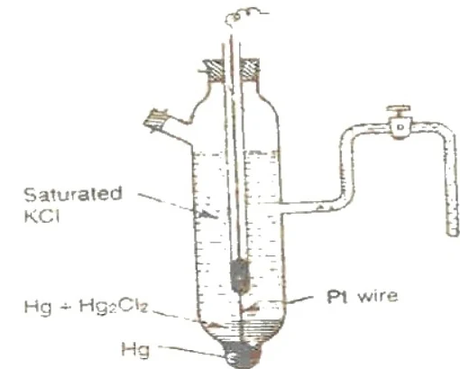
Figure: Diagram of a Calomel electrode
Diagram of a Calomel electrode. A schematic diagram showing labels for Saturated KCl, Hg + Hg2Cl2, Hg, and Pt wire. The electrode has an inner glass tube containing mercury and a paste of mercury and calomel, surrounded by a jacket of saturated potassium chloride solution.
Electrode Reaction:
Working of Calomel Electrode (Determination of Electrode Potential)
In order to measure the electrode potential of an electrode (e.g., Zn electrode), it is coupled with SCE using a digital voltmeter. The voltmeter reading will give the cell emf. The reduction potential of SCE is , which is higher than the reduction potential of (). Therefore, reduction reaction takes place at SCE.

Figure: Experimental setup for determining electrode potential using a calomel electrode coupled with a Zn electrode
Experimental setup for determining electrode potential using a calomel electrode coupled with a Zn electrode. A setup showing a Zn electrode in a beaker of ZnSO4(aq) connected via a digital voltmeter to a calomel electrode. Labels include Digital Voltmeter, Zn, ZnSO4(aq), Pt foil, Hg, Paste of Hg + Hg2Cl2, and Saturated KCl solution.
Cathode:
Anode:
The resultant cell can be represented as:
can be read directly from the voltmeter.
Advantages of Calomel Electrode
- It is very easy to set up.
- Its emf will not change with chemical reaction.
Numerical Example: Determine the electrode potential of calomel using Copper electrode.
Hint: Copper will act as cathode as its electrode potential is & Calomel as anode as its potential is (saturated).
Calomel at anode cell reaction:
Glass Electrode
- Glass electrode is an example of an ion selective electrode.
- It is a special type of glass with low melting point and high electrical conductivity.
- It consists of a thin glass bulb in which wire coated with is used as an internal reference electrode.
- It is then filled with solution. in the bulb furnishes a constant ion concentration.
- The electrode representation is written as:
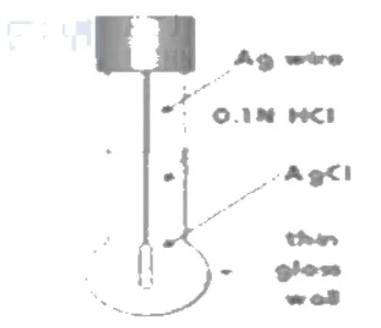
Figure: Diagram of a glass electrode
Diagram of a glass electrode. It shows a vertical cylindrical glass tube with a thin glass bulb at the bottom. Labels point to the following features from top to bottom: Ag wire (pointing to the internal wire), 0.1N HCl (pointing to the internal solution), AgCl (pointing to the coated portion of the wire), and thin glass wall (pointing to the bottom bulb).
- Here the glass membrane acts as an ion selective membrane sensitive to . So an ion exchange reaction occurs between singly charged cations of glass () & ions of solution. Finally an equilibrium is established between ions of glass & ions of solution.
The electrode reaction:
The Nernst equation for the electrode can be written as:
Determination of pH Using Glass Electrode
Glass electrode is used as an internal reference electrode. In order to determine the unknown pH of a solution, glass electrode is coupled with SCE and the resultant cell can be represented as:
The equation has the form of , representing a straight line having intercept and slope when we plot emf on -axis and pH on -axis. The constant and can be determined by calibrating the pH meter with two buffer solutions of known pH.
- Intercept ():
- Slope (): ,
Advantages of Glass Electrode
- It is very simple to operate.
- It can be used to find the of oxidising, reducing and even coloured solutions." }
Electrochemical Series and Its Applications
Bridge: Now that individual electrode potentials can be measured, we arrange them systematically to predict reaction feasibility and cell EMF.
The new idea: Arranging electrodes in order of reduction potential to quantitatively predict chemical reactivity and cell spontaneity.
Objectives: Define the electrochemical series and understand standard reduction potentials; Predict feasibility of redox reactions and metal displacement; Calculate standard cell EMF.
Concepts to teach: Electrochemical series, standard reduction potential, standard cell EMF, displacement reactions, equilibrium constant, spontaneity of redox reactions.
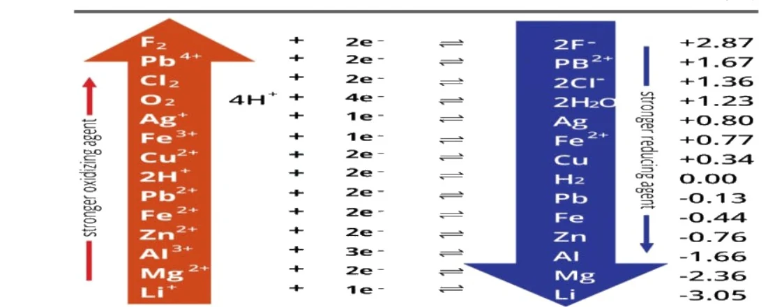
Figure: Electrochemical series showing half reactions and standard potentials
An electrochemical series table showing half reactions, electron transfers, and standard reduction potentials (V). The table has headers 'Half Reaction' and 'Standard Potential (V)'. On the left, an upward red arrow labelled 'stronger oxidizing agent' spans across half-reactions: F2 + 2e- (+2.87), Pb4+ + 2e- (+1.67), Cl2 + 2e- (+1.36), O2 + 4H+ + 4e- (+1.23), Ag+ + 1e- (+0.80), Fe3+ + 1e- (+0.77), Cu2+ + 2e- (+0.34), 2H+ + 2e- (0.00), Pb2+ + 2e- (-0.13), Fe2+ + 2e- (-0.44), Zn2+ + 2e- (-0.76), Al3+ + 3e- (-1.66), Mg2+ + 2e- (-2.36), Li+ + 1e- (-3.05). In the middle are equilibrium arrows and electron counts. On the right, a downward blue arrow labelled 'stronger reducing agent' spans the corresponding reduced species: 2F-, Pb2+, 2Cl-, 2H2O, Ag, Fe2+, Cu, H2, Pb, Fe, Zn, Al, Mg, Li with their respective standard potentials.
Electrochemical series showing half reactions and standard potentials. An electrochemical series table showing half reactions, electron transfers, and standard reduction potentials (V). The table has headers 'Half Reaction' and 'Standard Potential (V)'. On the left, an upward red arrow labelled 'stronger oxidizing agent' spans across half-reactions: (+2.87 V), (+1.67 V), (+1.36 V), (+1.23 V), (+0.80 V), (+0.77 V).
Applications of Electrochemical Series
- To know the relative ease of oxidation and reduction:
Greater the reduction potential, more easily the substance undergoes reduction and is a better oxidising agent (e.g., Fluorine, ). Similarly, greater the oxidation potential, more easily the substance undergoes oxidation and is a better reducing agent (e.g., Potassium, ). Symbol definitions and units: represents standard electrode potential in volts (). Temperature is assumed at with unit activities for species.
- To predict whether the metal will react with acid to give hydrogen gas:
Metals present above hydrogen in the electrochemical series can react with acids to give hydrogen gas. This is because these metals have a greater tendency to undergo oxidation with respect to hydrogen, since they have a negative reduction potential.
- To calculate the standard EMF of the cell:
represents standard cell potential in volts (). If we know the position of electrodes in the electrochemical series, we can easily predict which electrode can function as anode and which one can function as cathode.
- Displacement reactions
A metal with a lower reduction potential can displace a metal with a higher reduction potential from its salt solution. Zinc can displace copper from copper sulfate solution.
Calculation of Equilibrium Constant and Feasibility
- Calculation of Equilibrium Constant
By the equation:
where = equilibrium constant, = number of electrons transferred, and is the electrode potential in volts (). If the electrode potential is known, can be determined by the above equation.
- Feasibility of a Redox Reaction:
If is positive (+ve), then the redox reaction is spontaneous.
If is negative (-ve), then the redox reaction is non-spontaneous.
Calomel Electrode Reference System
- Since a standard hydrogen electrode is difficult to prepare and maintain, it is usually replaced by other reference electrodes, which are known as secondary reference electrodes.
- These are convenient to handle and are prepared easily.
- It consists of mercury at the bottom over which a paste of mercury-mercurous chloride () is placed.
- A solution of potassium chloride () is then placed over the paste.
- A platinum wire sealed in a glass tube helps in making the electrical contact.
- The electrode is connected with the help of the side tube on the left through a salt bridge with the other electrode to make a complete cell.
- The potential of the calomel electrode depends upon the concentration of the potassium chloride solution.
- If the potassium chloride solution is saturated, the electrode is known as a Saturated Calomel Electrode (SCE).
- The calomel electrode acts as either anode or cathode with respect to the other electrode connected to it.
Conductivity and Conductometric Measurements
Transitioning from potential measurements, this topic focuses on the flow of ions and the measurement of solution conductivity. The central idea is relating cell geometry and ion mobility to bulk solution conductivity via the cell constant.
Fundamentals for the Measurement of Conductivity
-
Ohm's Law: States that the current passing through a conductor is directly proportional to the potential difference. Where is current, is potential difference, and is resistance.
-
Resistance (): The measure of obstruction to the flow of current. Its SI unit is Ohm (). Where is specific resistance, is the length of the conductor, and is the cross-sectional area.
-
Conductance (): The reciprocal of resistance, representing how easily current flows.
-
Specific Resistance (Resistivity, ): The resistance of a conductor of unit length and unit area of cross-section, or the resistance of unit volume of a conductor. Its unit is .
-
Specific Conductance (Conductivity, ): The reciprocal of resistivity. It is also defined as the conductance of unit length and unit area of cross-section of a conductor. Its unit is . Where is the cell constant.
Cell Constant and Conductivity Cell
Cell Constant: In a conductivity cell, the distance between the two electrodes () and the area of the electrodes () are fixed. This geometric ratio is called the cell constant. The unit of the cell constant is or .
Conductivity Cell: A conductivity cell consists of two electrode plates coated with finely divided platinum black (to minimize polarization effects). These plates are welded to platinum wires sealed through two glass tubes. The tubes are rigidly fixed so that the distance between the electrodes remains unaltered.
Determination of Cell Constant: Although the cell constant may theoretically be obtained by measuring and , it is very difficult to measure the actual effective area precisely in small laboratory cells. In actual practice, the cell constant is measured by filling the conductivity cell with a solution of known conductivity, such as solution. The conductivity (specific conductance) of solution is at . By measuring the conductance of this solution in the given cell, the cell constant is determined:
Measurement of Conductivity Using a Digital Conductivity Meter
To measure conductivity, the conductivity cell is connected to a digital conductivity meter and the appropriate temperature is selected. The conductivity cell is then dipped into the sample solution contained in a beaker, ensuring that the cell is fully immersed. The conductance of the solution is measured by selecting the proper range switch (mili-Siemens or micro-Siemens).
The digital conductivity meter directly reads out the conductance. In these instruments, a AC is typically used to measure conductance to prevent polarization and compositional changes at the electrodes.
The conductivity of the sample solution is calculated using the relation:
Types of Electrochemical Cells
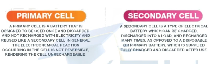
Figure: Primary Cell and Secondary Cell comparison boxes
Two side-by-side comparative text boxes describing types of electrochemical cells. The left box features an orange header with the text 'PRIMARY CELL' and contains the description: 'A PRIMARY CELL IS A BATTERY THAT IS DESIGNED TO BE USED ONCE AND DISCARDED, AND NOT RECHARGED WITH ELECTRICITY AND REUSED LIKE A SECONDARY CELL IN GENERAL. THE ELECTROCHEMICAL REACTION OCCURRING IN THE CELL IS NOT REVERSIBLE, RENDERING THE CELL UNRECHARGEABLE.' The right box features a pink header with the text 'SECONDARY CELL' and contains the description: 'A SECONDARY CELL IS A TYPE OF ELECTRICAL BATTERY WHICH CAN BE CHARGED, DISCHARGED INTO A LOAD, AND RECHARGED MANY TIMES, AS OPPOSED TO A DISPOSABLE OR PRIMARY BATTERY, WHICH IS SUPPLIED FULLY CHARGED AND DISCARDED AFTER USE.'
Lithium-Ion Cell
The lithium-ion cell is a rechargeable battery in which lithium ions move between the anode and cathode during charging and discharging. It is exceptionally popular due to the favorable characteristics of lithium: it possesses a high negative reduction potential and a lower atomic mass than any other alkali metal.
- Cathode (Positive Electrode): Made of a crystalline mixed oxide, such as . These crystals are typically synthesized via the hydrolysis of respective metal salts under hydrothermal conditions.
- Anode (Negative Electrode): Made of porous graphite, , which facilitates the intercalation of lithium ions.
- Electrolyte: A non-aqueous organic solution of lithium salts, such as or , providing ionic transport between the electrodes without reacting with metallic lithium.
Advanced Batteries and Fuel Cells
Bridge: Having explored standard galvanic cells, we now examine advanced high-energy storage systems and continuous energy conversion devices.
The new idea: Intercalation-based energy storage in lithium batteries and continuous reactant feed in fuel cells.
Lithium-Ion Battery Mechanisms
A Lithium-ion cell is a rechargeable battery that operates through the intercalation and de-intercalation of lithium ions between the anode and cathode materials during charging and discharging cycles.
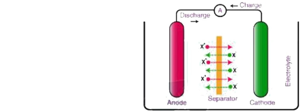
Figure: Diagram of a Lithium-ion cell showing Anode, Cathode, Separator, and Electrolyte with charge and discharge directions.
Diagram of a Lithium-ion cell showing Anode on the left (reddish cylinder), a Cathode on the right (green cylinder), a Separator in the middle with dotted green and red arrows labeled with x, and an Electrolyte filling the container. An external circuit with an ammeter (A) connects the two electrodes, with arrows indicating 'Discharge ->' towards the left and '<- Charge' towards the right.
- Case 1 (Construction): During cell construction, there is no net transportation of lithium ions between electrodes.
- Case 2 (Charging): When the cell is charging, an external potential forces some of the lithium ions () to transfer from the cathode to the anode. Considering number of lithium ions, the charging reaction is:
- Case 3 (Discharging): When the cell is discharging, lithium ions () spontaneously transfer from the anode back to the cathode:
Applications of Lithium-Ion Cells: Lithium-ion cells are widely utilized in mobile phones, tablets, laptops, electric vehicles, medical devices, and solar power backup storage units.
Hydrogen-Oxygen Fuel Cell
A fuel cell is an electrochemical conversion device that directly converts the chemical energy of a fuel and an oxidant into electrical energy via an external circuit, rather than by combustion. Reactants are supplied continuously from outside, allowing energy to be withdrawn indefinitely as long as the supply is maintained.
The overall cell reaction is an exothermic process:
Construction and Operating Conditions
- Electrodes: Two porous graphite electrodes impregnated with metal catalysts such as platinum.
- Electrolyte: A fabric-like matrix made of teflon-bonded silicon carbide dispersed with highly concentrated phosphoric acid () acts as an Arrhenius acid electrolyte to transport hydrogen ions ().
- Operating Parameters: Hydrogen and oxygen gases under high pressure () are continuously passed through the anodic and cathodic chambers respectively. The cell operates at temperatures between and to overcome the low ionic conductivity of phosphoric acid at lower temperatures. Cooling plates are used to maintain a stable operating temperature near .
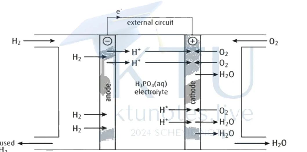
Figure: Diagram of a Hydrogen-Oxygen Acid Fuel Cell
Diagram of a hydrogen-oxygen fuel cell showing an external circuit with electron flow (e-) from anode (-) to cathode (+). Hydrogen (H2) enters on the left, unused H2 exits at the bottom left. Oxygen (O2) enters on the top right, and water (H2O) exits at the bottom right. The cell contains an H3PO4(aq) electrolyte, an anode on the left, and a cathode on the right. Protons (H+) and electrons (e-) move across the cell components as indicated by arrows.
Half-Cell Reactions (Acidic Medium)
At Anode: Hydrogen gas is oxidized to protons, releasing electrons that flow through the external circuit:
At Cathode: Oxygen gas is reduced to water by consuming protons transported through the electrolyte and electrons from the external circuit:
Net Cell Reaction:
Applications and Advantages
Hydrogen-oxygen fuel cells are primarily used in stationary power generators and military applications due to their stable operation and long lifetime. Unlike alkaline fuel cells, acid-based fuel cells possess high tolerance toward and , permitting their presence in the hydrogen and air feed without degrading cell performance.
Corrosion Mechanisms and Theories
Bridge: Understanding electrochemical cells and potentials allows us to analyze unwanted spontaneous electrochemical deterioration known as corrosion.
The new idea: Treating environmental degradation of metals as localized short-circuited electrochemical corrosion cells.
Objectives: Differentiate between dry and wet corrosion; Explain hydrogen evolution and oxygen absorption mechanisms in acidic and alkaline media; Compare electrochemical series with galvanic series
Introduction to Corrosion
Corrosion is the slow process of deterioration or destruction of the metal through the chemical or electrochemical changes taking place at its surface. Corrosion reactions are broadly categorized into two main types, which form the basis for the theories of corrosion:
- Dry corrosion (Chemical corrosion)
- Wet corrosion (Electrochemical corrosion)
1. Dry Corrosion (Chemical Corrosion)
Dry corrosion occurs via the direct chemical attack of atmospheric gases on a metal surface in the complete absence of moisture. It is further classified into three categories:
- Oxidation corrosion: Direct action of oxygen at high or low temperatures on metal surfaces, forming oxide scales.
- Corrosion by other gases: Direct chemical attack by corrosive gases such as , , , and .
- Liquid metal corrosion: Chemical interaction of flowing liquid metal at high temperatures on solid metal or alloy surfaces.
2. Wet Corrosion (Electrochemical Corrosion)
Wet corrosion occurs when a conducting liquid is in contact with a metal, or when two dissimilar metals or alloys are partially immersed in a conducting solution. This gives rise to microscopic or macroscopic electrochemical cells.
A. Hydrogen Evolution Corrosion
In Acid Medium
This type of corrosion occurs when metals are in contact with acidic solutions in the absence of sufficient oxygen concentration (e.g., iron or aluminum in contact with ). Hydrogen evolution corrosion takes place on iron immersed in an acid medium because the standard hydrogen electrode potential in an acid medium () is higher than the standard reduction potential of iron (). Consequently, hydrogen ions are discharged as hydrogen gas.
Anode Reaction:
Cathode Reaction:
Net Reaction:
Metals having higher negative reduction potentials (such as , , ) act as anodes and suffer corrosion, whereas metals with positive reduction potentials (such as , ) act as cathodes and receive galvanic protection.
In Alkaline Medium
Hydrogen evolution corrosion generally does not take place for iron immersed in an alkaline medium. This is because the hydrogen electrode potential in an alkaline medium () is lower than the reduction potential of iron ().
However, amphoteric metals like aluminum can undergo hydrogen evolution corrosion in alkaline media because the alkaline hydrogen electrode potential () is higher than the reduction potential of aluminum ().
Anode Reaction:
Cathode Reaction:
Corrosion Cell Potential:
B. Oxygen Absorption Corrosion
In Acid Medium
This occurs when metals are in contact with water containing dissolved oxygen in acidic or neutral environments (e.g., rusting of iron).
Anode Reaction:
Cathode Reaction:
Corrosion Cell Potential:
The ions produced can be further oxidized to in acidic or neutral environments:
The ions form an insoluble precipitate of , commonly known as yellow rust. If the amount of moisture is restricted, black rust (, or magnetite) is formed instead. This localized accumulation of rust leads to intense localized destruction known as pitting corrosion.
In Alkaline Medium
This occurs when metals are in contact with water containing dissolved oxygen under alkaline conditions.
Anode Reaction:
Cathode Reaction:
Corrosion Cell Potential:
Galvanic Series
Relative corrosion affinities of metals and alloys can be systematically evaluated using the galvanic series. This series is established by studying the corrosion behavior of metals and alloys in unpolluted seawater, accounting for surface conditions and oxide films. A metal higher in this series is more active/anodic and undergoes corrosion faster than a metal positioned below it.
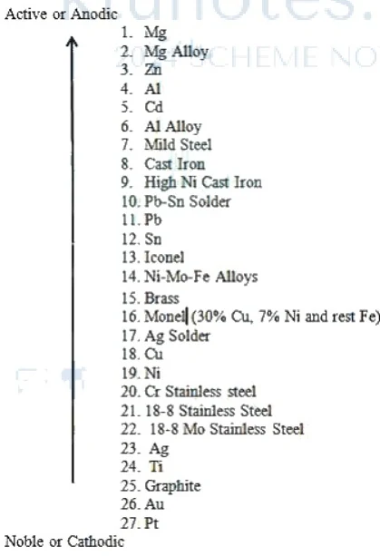
Figure: Galvanic series listing various metals and alloys from Active or Anodic to Noble or Cathodic
A vertical galvanic series list with an arrow pointing upwards. At the top of the arrow is the label 'Active or Anodic' and at the bottom is 'Noble or Cathodic'. The numbered list from 1 to 27 contains: 1. Mg, 2. Mg Alloy, 3. Zn, 4. Al, 5. Cd, 6. Al Alloy, 7. Mild Steel, 8. Cast Iron, 9. High Ni Cast Iron, 10. Pb-Sn Solder, 11. Pb, 12. Sn, 13. Inconel, 14. Ni-Mo-Fe Alloys, 15. Brass, 16. Monel (30% Cu, 7% Ni and rest Fe), 17. Ag Solder, 18. Cu, 19. Ni, 20. Cr Stainless steel, 21. 18-8 Stainless Steel, 22. 18-8 Mo Stainless Steel, 23. Ag, 24. Ti, 25. Graphite, 26. Au, 27. Pt.
Figure: Galvanic series listing various metals and alloys from Active or Anodic to Noble or Cathodic (showing 1. , 2. Alloy, 3. , 4. , 5. , 6. Alloy, 7. Mild Steel, 8. Cast Iron, 9. High Ni Cast Iron, 10. Pb-Sn Solder, 11. Pb, 12. Sn, 13. Inconel, 14. Ni-Mo-Fe Alloys, 15. Brass, 16. Monel). Note that the exact position of a metal when alloyed differs from that of the pure metal.
Comparison: Electrochemical Series vs. Galvanic Series
| Electrochemical Series | Galvanic Series |
|---|---|
| is measured only for pure metals and nonmetals. | is measured for metals and engineering alloys. |
| is measured by dipping pure metals in their salt solution. | is measured by dipping metals and alloys in unpolluted seawater. |
| Standard Hydrogen Electrode (SHE) is used as the reference electrode. | Calomel electrode is typically used as the reference electrode. |
| Position of the pure elements is fixed. | Position of metals and alloys may vary based on environmental conditions. |
| It predicts relative thermodynamic displacement tendencies. | It predicts practical corrosion tendencies in real-world aqueous environments. |
Corrosion Control and Metal Finishing
Bridge: With the mechanisms of corrosion established, we now explore methods to protect metals and apply protective surface coatings.
The new idea: Forcing a corroding metal to act as a cathode or depositing protective metallic coatings via electrolytic and autocatalytic routes.
Cathodic Protection
In cathodic protection, the metal to be protected is made to act as a cathode so that corrosion ceases. This is achieved through two principal methods:
a) Sacrificial anodic protection: The metal to be protected is connected by an external metallic wire to a more anodic (active) metal. The more active metal undergoes oxidation and sacrifices itself while the protected metal remains intact. Common sacrificial metals include magnesium (), zinc (), aluminum (), and their alloys.
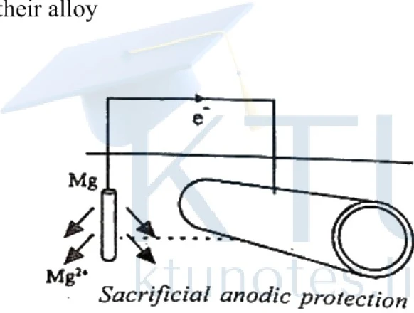
Figure: Diagram showing sacrificial anodic protection of a metal pipe using a magnesium anode connected by a wire.
Diagram showing sacrificial anodic protection. A cylindrical pipe is connected by an external wire to a vertical magnesium (Mg) block. Arrows indicate electrons (e-) flowing from the Mg block to the pipe, and oxidation of Mg to Mg2+ ions near the block. The caption reads 'Sacrificial anodic protection'.
b) Impressed current cathodic protection: An external direct current is applied in the opposite direction to nullify the natural corrosion current, converting the corroding structure from an anode to a cathode. The required direct current is supplied via a DC power source connected to an insoluble auxiliary anode (such as graphite or high-silica iron) buried in the ground or immersed in the liquid. This method is widely used for protecting open water box coolers, storage tanks, and buried pipelines.
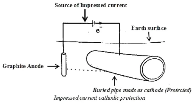
Figure: Diagram of impressed current cathodic protection
Diagram of impressed current cathodic protection. A schematic diagram showing impressed current cathodic protection. It features a horizontal line representing the Earth surface with an arrow pointing down labelled 'Earth surface'. Below it is a buried pipe labelled 'Buried pipe made as cathode (Protected)' with a vertical arrow pointing down to it. To the left, a vertical rod is labelled 'Graphite Anode' with an arrow pointing to it. At the top, a circuit shows a source of impressed current with a DC voltage source symbol (longer and shorter parallel lines) labelled 'Source of Impressed current' with an arrow pointing to it, and electron flow 'e-' indicated. The caption below reads 'Impressed current cathodic protection'.
Electroless Plating (Autocatalytic Plating)
Electroless plating deposits a metal coating from its salt solution onto a catalytically active surface using a reducing agent, without requiring external electrical energy. The substrate is immersed in a plating bath containing metal ions, a complexing agent, and a reducing agent. The reducing agent chemically reduces the metal ions to elemental metal, which plates out uniformly over the catalytic substrate.
Electroless Copper Plating
The article to be plated is immersed in a bath containing copper sulfate () as the copper source, formaldehyde () as the reducing agent, sodium hydroxide () as a buffer, and a complexing reagent. Air is bubbled through the medium to regulate cuprous oxide formation.
Oxidation reaction:
Reduction reaction:
Net reaction:
Applications of Electroless Copper Plating:
- Metallizing printed circuit boards (PCBs).
- Plating on non-conductive substrates.
- Decorative plating on plastics.
Advantages:
- Produces even, uniform coatings regardless of geometry.
- Operates without external electrical power.
- Enhances hardness, strength, ductility, and corrosion resistance.
Disadvantages:
- Formaldehyde reducing agent is a human health hazard.
- Bath instability requires careful process control.
Electroplating
Electroplating is an industrial method for applying metallic coatings by passing a direct current through an electrolytic bath containing soluble salts of the coating metal.
Theory of Electroplating: The object to be plated acts as the cathode, while the anode is either made of the coating metal itself or an inert conductor (such as graphite). When a direct current flows, metal ions migrate to the cathode and deposit as a uniform film.
Objectives of Electroplating:
- Increase corrosion, chemical, and wear resistance.
- Improve surface hardness and physical appearance.
- Elevate decorative and commercial value.
Copper Electroplating
Before plating, the article is cleaned with an organic solvent to remove grease, followed by treatment with dilute or dilute to eliminate surface oxides.
- Cathode: Cleaned article ()
- Anode: Pure copper rod ()
- Electrolyte: Aqueous copper sulfate () solution.
When an inert anode (e.g., graphite) is used instead of active copper, the anode reaction generates oxygen gas: In this setup, copper salt is added continuously to maintain bath concentration.
Applications of Copper Electroplating:
- Used in the automotive industry as part of multi-layer protective coatings (--) on steel.
- Applied to decorative items, kitchenware, and jewelry for aesthetic enhancement.