
Dielectrics - Module 3
Learn the fundamental principles of dielectric materials, polarization mechanisms, internal fields, Clausius-Mossotti relation, and dielectric breakdown phenomena.
Before you start: Basic electrostatics and Gauss's law; Concept of electric dipole moment and electric field intensity.
Your path through this module
- Fundamentals of Dielectrics and Relative Permittivity: Dielectrics store electrical energy through polarization rather than free conduction.
- Polarization and Susceptibility: Polarization quantifies the density of induced dipole moments per unit volume.
- Relation Between Polarization, Displacement, and Field: Displacement current and bound surface charges link external fields directly to internal material polarization.
- Types of Polarization: Total polarization is the sum of distinct microscopic mechanisms operating at atomic, ionic, and molecular levels.
- Internal Field in Solids and Liquids: The local field experienced by a molecule differs from the macroscopic applied field due to surrounding polarization charges.
- Clausius-Mossotti Relation: The Clausius-Mossotti relation bridges microscopic polarizability with macroscopic dielectric constants.
- Dielectric Breakdown and Dielectric Loss: Excessive electric fields or alternating stresses cause permanent material breakdown and energy dissipation (dielectric loss).
Fundamentals of Dielectrics and Relative Permittivity
Bridge: Having understood basic electrostatics, we now examine insulating materials that store charge under an electric field.
The new idea: Dielectrics store electrical energy through polarization rather than free conduction.
Objectives: Define dielectric materials and give examples; Explain dielectric constant and relative permittivity.
1. What are Dielectric Materials? Give Examples
Dielectrics are materials which have poor electrical conductivity but inherit an ability to store an electrical charge due to dielectric polarization. When dielectric materials are placed in an electric field, they modify the electric field and they themselves undergo appreciable changes because of which they act as stores of electric charges. When charge storage is the main function, the materials are called dielectrics.
Key characteristics of dielectrics:
- Forbidden Energy Gap (): The forbidden gap is very high in dielectrics.
- Resistivity: The resistivity of an ideal dielectric is infinitely high. However, in practice, dielectric resistivity ranges from to , because they conduct electric current to a negligible extent.
Examples: Plastic, Mica, Porcelain, etc.
2. Dielectric Constant or Relative Permittivity ()
The dielectric constant of a material is defined as the ratio of the permittivity of the medium () to the permittivity of free space ().
Physical Interpretation and Properties:
- Dimensionless Quantity: Relative permittivity is a purely dimensionless quantity.
- Magnitude: It is always greater than unity in the case of dielectrics.
- Independence: It is independent of the size and shape of the dielectric.
- Utility: The measure of the dielectric constant or relative permittivity of a material gives the fundamental properties of a dielectric material.
- Reference Value: The dielectric constant of air is approximately equal to one.
Polarization and Susceptibility
Bridge and Objectives
Building on the definition of dielectric constant, we study how an external electric field induces dipole moments inside the material. The new idea is that polarization quantifies the density of induced dipole moments per unit volume. Our objectives are to define polarization and polarizability, and to relate polarization to dielectric susceptibility and relative permittivity.
Concepts and Definitions
When charges of opposite polarity are induced on the surface of a dielectric, the dielectric is said to be polarized, and this effect is known as Polarization.
- Polarization (): Defined as the net induced dipole moment per unit volume of a polarized dielectric material. The SI unit of polarization is .
- Polarizability ( or \boldsymbol{\frac{}{}\text{or }\text{\textbf{\textit{\boldsymbol{\text{\textalpha}}}}}}): A measure of how easily a molecule or atom is polarized by an electric field.
- Dielectric Susceptibility (\boldsymbol{\text{\textbf{\textit{\boldsymbol{\text{\textchi}}}}}}): A dimensionless proportionality constant that characterizes the ease with which a dielectric material can be polarized by an external electric field.
Mathematical Derivations and Relations
The macroscopic polarization of a dielectric is proportional to the number of polarized atoms or molecules per unit volume and the dipole moment of a single atom or molecule :
Since the induced dipole moment of a single atom or molecule is proportional to the local electric field , we write:
Substituting into the polarization equation gives:
Here, is the total polarizability, which consists of three distinct microscopic contributions:
where is electronic polarizability, is ionic polarizability, and is orientation polarizability.
Dielectric susceptibility links the polarization directly to the applied electric field and the permittivity of free space :
To find the connection between susceptibility and the relative permittivity (dielectric constant) , we begin with the fundamental constitutive relation for electric displacement :
Using the definition , we substitute and into the equation:
Dividing through by yields the relation between the dielectric constant and dielectric susceptibility:
Relation Between Polarization, Displacement, and Field
Bridge and Objectives
Having defined polarization macroscopically, we now use Gauss's law to connect it with electric displacement and applied fields. Displacement current and bound surface charges link external fields directly to internal material polarization.
- Objectives: Derive the relation between displacement vector, electric field, and polarization using Gauss's law; Express polarization as a function of relative permittivity.
Concepts and Derivation
1. Electric Field Without Dielectric
For a parallel plate capacitor without a dielectric, let the free charges on the two plates be and , and the electric field intensity between the plates be . According to Gauss's law:
2. Electric Field With Dielectric
Let a dielectric slab be placed between the two plates. Due to polarization, equal and opposite bound charges are induced on the two faces of the slab. The total charge enclosed by the Gaussian surface becomes . Using Gauss's law:
3. Defining Displacement and Polarization
- Electric Displacement (Free surface charge density): []
- Dielectric Polarization (Induced surface charge density): []
Substituting these definitions into equation :
In linear, isotropic dielectric media, the electric displacement is also defined as , where .
Equation gives the fundamental relation between polarization and the dielectric constant (relative permittivity ). The general vector form of the relation is:

Figure: Diagram showing a dielectric slab between two plates with polarization and displacement vectors
A diagram showing a rectangular dielectric slab placed horizontally between two charged regions. A top horizontal line has '+' signs above and '-' signs below it. A bottom horizontal line has '+' signs above the bottom surface of the slab and '-' signs below it. On the left, four vertical lines with downward-pointing arrows pass through the slab, labelled 'D' at the bottom. On the right, four vertical lines with upward-pointing arrows inside the slab point upwards towards the top surface, labelled 'P' below the bottom region.
Physical Interpretation
- : The reduced macroscopic electric field inside the dielectric due to the opposing internal polarization field.
- : The material's response vector, quantifying the induced dipole moment per unit volume.
- : The electric displacement vector, which is independent of the dielectric medium and determined solely by the free charges on the capacitor plates.
Types of Polarization
Bridge: Having established macroscopic relations, we investigate the microscopic mechanisms responsible for polarization.
The new idea: Total polarization is the sum of distinct microscopic mechanisms operating at atomic, ionic, and molecular levels.
1. Electronic Polarization
The electronic polarization arises due to the displacement of the electron cloud of an atom relative to its nucleus in the presence of an applied electric field.
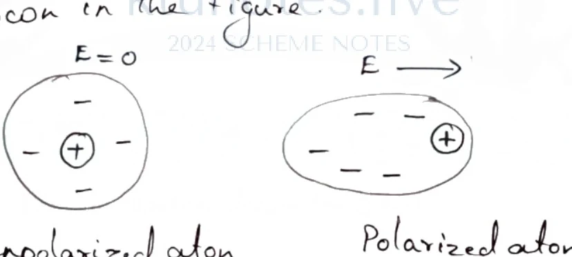
Figure: Electronic Polarisation diagrams showing unpolarized atom with E=0 and polarized atom with E pointing right
Two diagrams illustrating electronic polarisation. The left diagram is labelled 'unpolarized atom' with 'E = 0' above it, showing a circular electron cloud with negative signs and a central positive nucleus represented by a plus sign inside a small circle. The right diagram is labelled 'Polarized atom' with an electric field arrow pointing right labelled 'E' above it, showing an oval-shaped (horizontally elongated) electron cloud with negative signs and a central positive nucleus shifted to the right side inside a small circle.
It is the polarization of a single atom in a dielectric material. The polarization as well as the dielectric constant of a material at optical frequency results mainly from electronic polarizability. The electronic polarization is proportional to electric field and is given by:
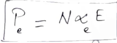
Figure: Equation for electronic polarisation
An equation enclosed in a rectangular box showing the relation for electronic polarisation: P_e = N ̒_e E, where P_e is the electronic polarisation, N is the number of atoms per unit volume, ̒_e is the electronic polarizability, and E is the electric field.
where is the number of atoms per unit volume and is the electronic polarizability. The electronic polarizability is related to the atomic radius by:
Key Characteristics:
- It increases with an increase in the volume of the atom.
- It is independent of temperature.
- It is mostly exhibited by monoatomic gases such as Helium, Neon, Argon, etc.
2. Ionic Polarization
The ionic polarization arises due to the displacement of a charged ion relative to other ions in a solid. When an electric field is applied to an ionic crystal such as , , , etc., the positive and negative ions are displaced in opposite directions.
The ionic polarization produced for a crystal having dipoles per unit volume is given by:
where is the ionic polarizability, defined as:
where is electronic charge, is the natural frequency of ionic oscillation, and are the masses of positive and negative ions respectively.
Key Characteristics:
- It does not depend on temperature.
- The magnitude of ionic polarization is generally larger than electronic polarization.
- In addition to ionic polarization, the ionic molecule also possesses electronic polarization due to the shifting of electron clouds.
3. Orientation Polarization
Orientation polarization is exhibited by polar molecules such as , , phenol, etc. Polar molecules have a permanent dipole moment even in the absence of an electric field. In the absence of an electric field, the permanent dipoles are oriented randomly so that the net dipole moment is zero.

Figure: Diagram showing random dipole orientations with E=0 and no applied field
A rectangular box representing a dielectric medium containing several small arrows pointing in random, varying directions. Below the box, the text reads E = 0 No applied field.
When an electric field is applied to a polar molecule, the dipole experiences a torque and aligns parallel to the applied field.
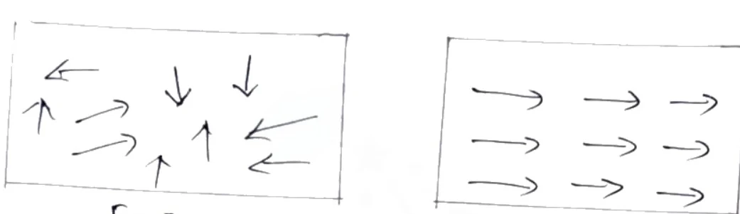
Figure: Diagram showing aligned dipoles with E > 0 with field
A rectangular box representing a dielectric medium containing three rows of three arrows, where all nine arrows point horizontally to the right. Below the box, the text reads E > 0 with field.
Orientation polarization, , is expressed as:
where is the orientation polarizability, given by:
where is the permanent dipole moment, is Boltzmann's constant, and is absolute temperature.
Key Characteristic: Orientation polarization depends strongly on temperature; as the temperature of the material increases, the thermal energy tends to disturb the alignment.
4. Space Charge Polarization
Space charge polarization occurs due to the presence of a dielectric medium placed between two electrodes. In the absence of an electric field, positive and negative charges are not separated. When an electric field is applied, positive charges accumulate near the negative electrode and negative charges near the positive electrode. Space charge polarization is defined as the redistribution of charges due to the applied electric field where charges accumulate on the surface or interfaces.
Total Polarization
The total polarization is the sum of electronic, ionic, and orientation polarizations. In the calculation of total polarization, space charge polarization is typically omitted as it occurs primarily at interfaces and is relatively small.
Internal Field in Solids and Liquids
The resultant electric field experienced by an atom or molecule inside a dielectric under an external electric field is called an internal field or local electric field (). The internal field differs from the macroscopic applied field because it accounts for the individual microscopic fields surrounding the molecule inside the dielectric.
Internal Field in Solids and Liquids
Bridge
Having studied polarization types, we now calculate the actual microscopic field experienced by an atom inside a dielectric.
The New Idea
The local field experienced by a molecule differs from the macroscopic applied field due to surrounding polarization charges. When a dielectric is placed in an external electric field, each molecule experiences an effective electric field, known as the internal field or local field (), which is generally different from the macroscopic applied electric field ().
Objectives
- Define the internal (local) electric field.
- Evaluate individual field components () inside a spherical cavity.
- Derive the total internal field expression.
Concepts and Field Components
To calculate the internal field acting on a particular molecule, we imagine carving out a microscopic spherical cavity around the molecule under consideration. The total internal field at the center of this cavity is given by the superposition of four distinct electric field components:
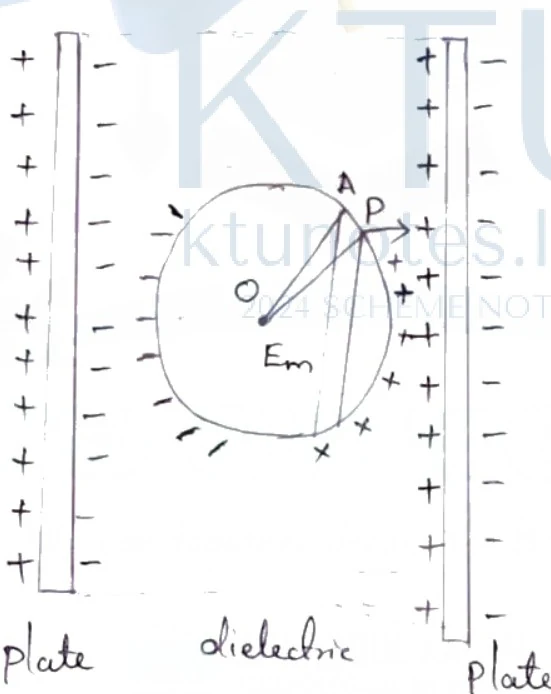
Figure: Internal field diagram between two plates with a dielectric sphere inside
Internal field diagram between two parallel plates with a dielectric medium containing an imaginary spherical cavity. The left plate has positive charges (+) and the right plate has negative charges (-), both labelled 'plate' at the bottom, with 'dielectric' written in the region between them. Inside the dielectric, a spherical cavity is shown with center O, a point A on the upper surface, and a radius line OA with label P near the surface. Charges are distributed along the cavity walls (positive on the right inner side, negative on the left inner side). The internal field Em is labeled inside the cavity.
1. Applied Field Component ()
It is the intensity of the electric field produced by the free charges on the plates of the capacitor. It is given by:
where is the surface charge density on the capacitor plates and is the permittivity of free space. Let be the intensity of the electric field in the dielectric medium due to the applied field. Using the fundamental dielectric displacement relation , where is the polarization vector:
2. Depolarizing Field ()
It is the electric field produced by the bound polarized surface charges on the dielectric slab boundaries. This field opposes the applied field and is called the depolarizing field:
The negative sign indicates that acts in a direction opposite to the applied field .
3. Cavity Field ()
It is the electric field acting on the molecule at the center of the imaginary spherical cavity due to the bound charges distributed on the surface of the cavity itself. For a uniform isotropic dielectric containing a spherical cavity, integration over the cavity surface yields:
4. Dipole Field in Cavity ()
It is the electric field due to all the individual permanent or induced atomic/molecular dipoles located inside the spherical cavity. This component depends entirely on the local crystal symmetry and atomic arrangement. For a completely isotropic and symmetric dielectric medium, the contributions cancel out symmetrically, giving:
Derivation of Total Internal Field
Substituting the individual components , , , and into the master equation:
This is the definitive expression for the internal field (or local field) experienced by an atom or molecule in a solid or liquid dielectric.
Clausius-Mossotti Relation
Bridge and Objectives
With the internal field expression established, we can connect microscopic atomic properties to macroscopic observable constants. The Clausius-Mossotti relation bridges microscopic polarizability with macroscopic dielectric constants.
Objectives:
- Relate macroscopic dielectric constant to microscopic atomic polarizability.
- Derive the Clausius-Mossotti equation step by step.
Concepts to Teach
- Clausius-Mossotti Relation: An equation connecting the macroscopic relative permittivity () of a dielectric material to the microscopic polarizability () of its constituent atoms or molecules and the number density ().
- Linking Polarizability to Relative Permittivity: Combines macroscopic definitions of polarization with microscopic local field equations.
- Local Field Substitution: Utilizing the Lorentz internal field expression to eliminate the microscopic local field in favor of the applied macroscopic field and polarization.
Derivation of the Clausius-Mossotti Equation
The dipole moment of a single atom is proportional to the local field or internal field:
where is the polarizability of the atom and is the internal (local) field. The total polarization for atoms per unit volume is given by:
Rearranging for polarizability :
Recall the Lorentz internal field expression in solids and liquids:
Substitute the value of into equation (3):
From macroscopic dielectric theory, polarization is also related to the applied electric field and relative permittivity by:
Solving for the applied field :
Substitute equation (6) into equation (4):
Factoring out in the denominator:
Rearranging terms to isolate macroscopic and microscopic constants:
Simplifying the complex fraction in the denominator:
Finally, rearranging the terms yields the Clausius-Mossotti relation:
Introduction to Dielectric Breakdown
When a voltage is applied to a dielectric material, it can withstand up to a maximum field intensity, beyond which structural damage occurs, resulting in permanent failure. This phenomenon in which the dielectric material fails to resist large applied voltages is known as dielectric breakdown, and the corresponding voltage is known as the breakdown voltage.
Dielectric Breakdown and Dielectric Loss
Bridge: Having examined normal dielectric behavior and polarization, we finally study the limits of material durability and energy dissipation.
The new idea: Excessive electric fields or alternating stresses cause permanent material breakdown and energy dissipation (dielectric loss).
Objectives: Define dielectric breakdown and list its types; Explain intrinsic, thermal, electrochemical, discharge, and defect breakdowns; Define dielectric loss and power loss in alternating fields.
1. Dielectric Breakdown
Dielectric breakdown occurs when a dielectric material loses its insulating properties and permits a large conduction current to flow under the influence of an excessively high electric field. The primary mechanisms of breakdown include:
- Intrinsic Breakdown: In a pure dielectric, the valence band is separated from the conduction band by a very large band gap. When subjected to a very large electric field, valence electrons acquire sufficient energy to cross the energy gap and enter the conduction band, producing a large current.
- Characteristics: Occurs at very high electric fields, happens at ordinary temperatures, is typically observed in thin samples, and has a breakdown time on the order of microseconds ().-
- Thermal Breakdown: Caused by internal heat generated within the dielectric when an electric field is applied. If the rate of heat generation exceeds the rate of heat dissipation, the excess heat causes permanent material destruction.
- Characteristics: Occurs at high temperatures, has a breakdown time on the order of milliseconds (), exhibits lower breakdown strength in alternating current (AC) fields, and depends strongly on the size and shape of the sample.
- Electrochemical Breakdown: Closely related to thermal breakdown. Elevated temperatures increase ion mobility, triggering electrochemical reactions and leakage currents that degrade insulation resistance until breakdown occurs.
- Characteristics: Depends heavily on ion concentration and the magnitude of leakage current, and occurs at ordinary temperatures.
- Discharge Breakdown: Caused by gas- or liquid-filled cavities and voids within the bulk dielectric. When subjected to high voltages, these pockets ionize, producing localized ionization currents that ultimately cause complete material failure.
- Defect Breakdown: Caused by structural surface defects such as cracks, pores, or impurity clusters that concentrate the electric field and provide localized pathways for failure.
2. Dielectric Loss and Power Loss in Alternating Fields
When a dielectric material is placed in an alternating (AC) electric field, electrical energy is absorbed by the medium and partially dissipated as heat. This dissipation is known as dielectric loss, and it arises from the continuous reversal of atomic and molecular dipoles under the alternating positive and negative field cycles.
The dielectric power loss is given by:
where:
- = applied alternating voltage ()
- = angular frequency of the applied field ()
- = capacitance of the dielectric capacitor ()
- = dielectric loss tangent or power factor of the dielectric (dimensionless)
Thus, for fixed values of voltage , angular frequency , and capacitance , the power loss depends directly on the loss tangent of the dielectric medium.